The Compact Disc Digital Audio (CD-DA) was developed by Philips and Sony in the 1970s and introduced on the market in 1982. The specifications of the CD-DA, the "Red Book" (IEC 908), are sold by Philips, but a simplified version can be found under the reference ECMA-130, which can be downloaded in PDF format from www.ecma.ch.
The Audio CD contains a maximum of 99 tracks. Each track lasts at least 4 seconds. The tracks are chained together (in the case of concerts) or can be separated with a pause. Each track can be divided into 99 indexes. Usually a track has two indexes, one for the pause and one for the music. The indexes have not really found their place, they could have been used to find highlights in a piece of music.
Digitization
The Compact Disc uses a digital technique to store a stereo audio signal on a 12 cm polycarbonate disc. Digitization consists of measuring the amplitude of a signal at regular intervals. The disc therefore saves the samples as a sequence of binary numbers (sequence of 0 and 1).
Manufacturing of Audio CDs
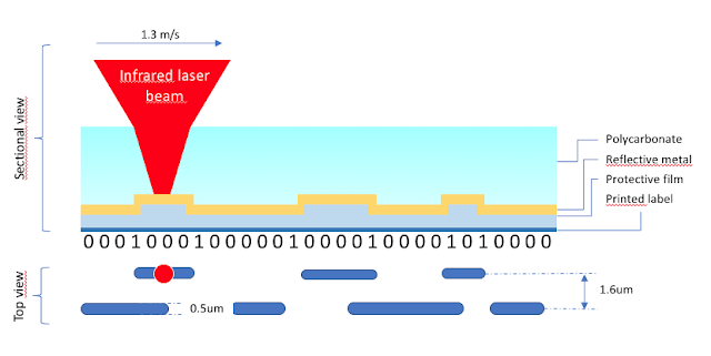
Audio CDs are manufactured by injecting a 1.2 mm polycarbonate substrate onto a matrix representing the digital tracks in relief. This layer is then covered with a reflective metallization of 50 to 100 nm (silver and more generally aluminum). A plastic layer with a thickness of 1000 to 3000 nm is added to protect the metallization. Finally, the label can be printed.
The binary sequences are represented by micropits in the substrate. The transition between a flat area and a microwell indicates a binary 1. Without a transition a binary 0 is read.
 |
| Section of a CD. |
The following series of photos is offered to us by Guillaume Sudant whom we thank very much. They were taken with a scanning electron microscope. You can visit his site and discover other fantastic images: http://semgallery.free.fr/
 |
| Vinyl record with 80x magnification. |
 |
| Compact Disk magnified 7243 times. |
Here is our Compact Disk magnified 7243 times. You can clearly see the small metallization domes more or less long. The distance between the tracks is 1.6 micrometer. The width of the cells is 0.5 micrometer.
 |
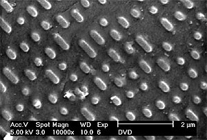
| DVD magnified 10000 times. |
And here is a picture of the surface of a DVD magnified 10000 times. The distance between the tracks went from 1.6 to 0.74 micrometer. The width of the cells is still 0.5 micrometer. It is easy to imagine the fragility of this structure.
Sampling
The audio signal is digitized on 16 bits per channel (right and left). Digitization consists of measuring the signal 44,100 times per second and encoding this value in binary on 16-bit words per channel.
The 16 bits make it possible to distinguish 2 exponents 16 = 65 536 different levels. The theoretical signal to noise ratio is given by the expression S/N = (6.02n + 1.76) in dB. Let 98 dB for 16 bits.
The audio bit rate of the CD is therefore 44.1 kHz * 16 bits * 2 channels = 1.41 Mbit/s.
Setting up a frame
The audio stream on the CD is divided into frames. One frame contains 6 sampling periods. It therefore contains 12 words of 16 bits, i.e. 192 bits. The raw frame has the following form: L1 R1 L2 R2 L3 R3 L4 R4 L5 R5 L6 R6 (L for left, R for right).
To this raw frame we will add an 8 byte CIRC error correction code, then a control byte. The frame is then encoded in EFM (transformation of the 8 bits bytes into 14 bits). Then each block of 14 bits is assembled with the following one thanks to 3 additional bits. Finally, the frame is completed by 27 synchronization bits.
Size of the final frame Nbr of bits (Total 588 bits)
- 24 x 8-bit: 192-bit audio signal
- 8-bit control: 8 bits
- 8 x 8 bits: 64-bit parity
- 27-bit sync
- (24 + 1 + 8 ) x 6 EFM: 198 bits
- (24 + 1 + 8 ) x 3 assembly: 99 bits
 |
| Elaboration of a Compact Disc frame. |
The 192 audio bits are therefore represented on the disc by a sequence of 588 bits, a ratio of 3.
 |
| Compact Disc frame. |
Error Correction Codes (CIRC)
The CIRC code (Cross Interleaved Reed-Solomon (Irving Reed and Gustave Solomon 1960)) is the error correction code of the Compact Disc consisting of two crossed Reed-Solomon codes C1 and C2. Each code has 4 bytes of parity for 24 bytes of audio. The complete frame thus comprises 8 bytes of parity.
The first step of the CIRC code consists in delaying by two frames the odd 16-bit words (L1 R1 L3 R3 L5 R5).
The second step mixes the 16-bit words in the following order: L1 L3 L5 R1 R3 R5 L2 L4 L6 R2 R4 R6.
The third step calculates the 4-byte C2 code. The frame thus takes the following form : L1 L3 L5 R1 R3 R5 C2 C2 L2 L4 L6 R2 R4 R6.
The fourth step delays by 4xD frames (D varying from 0 to 27) the bytes of the frame. The first byte of L1 is thus not delayed, the second byte of L1 is delayed by 4 frames, the first byte of L3 is delayed by 8 frames, etc.
The fifth step calculates the 4-byte C1 code. The frame thus takes the following form : L1 L3 L5 R1 R3 R5 C2 C2 L2 L4 L6 R2 R4 R6 C1 C1.
The sixth step delays the odd bytes of a frame. The first byte of L1 is thus delayed by one frame, the second byte of L1 is not delayed, the first byte of L3 is delayed by one frame, etc.
Finally the bytes of codes C1 and C2 are inverted.
Time distribution
Note that a frame n actually contains the bytes of the raw frames n-3 to n-108. Six successive audio samples are therefore spread over more than 100 frames recorded on the disk. If we imagine that one frame occupies approximately 0.176 mm on the disc (588 bits x 0.3 um), the 6 samples will be spread over more than 19 mm.
 |
| Writing a frame on a CD-DA. |
Frame coding elements
Control word
Each frame contains an 8-bit control word. By assembling the control word over 98 frames, an additional channel for data transmission is obtained.
On the Audio CD, only the first two bits of each byte are used (channels P and Q). Channel P indicates the presence of an audio track or an unrecorded area. Channel Q contains the following information:
- a pre-emphasis indication (increase of the treble level before burning - note that some players do not know how to process this information),
- the track number,
- the starting position of the track,
- the duration of the track,
- the time elapsed since the beginning of the disc.
Pre-emphasis
Early CD players had only 14-bit decoders instead of the 16-bit standard. The signal-to-noise ratio was therefore less good with small treble signals (quantization errors). To avoid this issue the standard allows to increase the amplitude of the high frequency signals (Pre-emphasis) before writing CDs and then to restore the correct signal after reading the CD and digital to analog conversion (de-emphasis). The standard thus specifies the use of a 15/50µs filter whose correction curve is reproduced below. This emphasis can be found on older editions of some CDs.
 |
| De-Emphasis Curve (Source Cirrus Logic) |
 |
| Same track recorded with (red) and without (blue) pre-emphasis (Source Pierre Verany). |
EFM Modulation
EFM (Eight to Fourteen Modulation) transforms 8-bit bytes into 14-bit words.
This coding allows the suppression of 1-bit sequences, because a 1-bit is detected by the rising edge and not by the value of the signal detected by the laser. It also minimizes repetitive 010 transitions, sources of reading error (each bit at 1 must be separated from the next by 2 to 10 bits at 0).
EFM coding also makes it possible to reduce large sequences of identical bits. This is because while the digital signal recorded on the CD reproduces the audio signal, it also provides synchronization to the playback mechanism.
For example:
- The binary word 1111 1111 is encoded in EFM 0010 0000 0100 01
- The binary word 1010 1010 is encoded in EFM 1001 0001 0010 01
Merging bits
The 3 assembly bits are used to enable the bit allocation rule (2 to 10 bits at 0 between each bit at 1) to be respected between two 14-bit words. They also make it possible to reduce the average digital value of the signal. These bits are calculated for each block of 14 bits.
The synchronization word
Each frame contains a 27-bit sync word (100000000001000000000010 + 3 assembly bits). The synchro allows to identify the position of a frame in the bitstream.
Error classification
When reading data from the CD, two types of errors may occur: Single errors (one or a few bits in error) and burst errors (several successive words in error). Point errors are caused by manufacturing defects or reading errors, while burst errors are caused by dust, fingerprints or scratches.
Sources of error
Manufacturing defects of the CD:
- micro bubble in the transparent layer of the disc,
- black spot (particle inserted in the substrate, or hole in the metallization,
- disc surface defect,
- failure to respect the mechanical characteristics (centering, track spacing, temperature resistance, etc.),
- non-respect of the recording speed.
- dust,
- scratches,
- fingerprints or any other trace.
- Loss of track tracking,
- laser source disturbed,
- Disc rotation speed is out of adjustment.
- micro bubble < 100 µm,
- black spot < 200 µm,
- distance between two defects < 20 mm.
Error definition
A byte will be considered in error if one or more bits are erroneous. A frame will be considered in error if it contains at least one byte in error.
BER: BER (Bit Error rate) is the number of bits in error relative to a total number of bits. Optical systems can handle a BER from 10-5 to 10-3. BER = BLER / 153600.
BLER : The Block Error Rate (BLER) is a unit of measurement for CD quality standardized by the "Red Book". It represents the maximum number of error frames per second detectable by code C1. The Audio CD specifications recommend that players support a BLER of at least 220 for a period of 10 seconds. Good quality discs should have a BLER of less than 50 or better10.
Burst: The number of consecutive frames with at least one error at the input of decoder C1 is called Burst. The specifications state that the burst must not exceed 7 frames.
Drop-out: A drop-out corresponds to an absence of information on the disk. It can be caused by a manufacturing defect, a concentric scratch or a large stain. In this case, it is several frames that are missing and not just a few bits that are in error. The depth of a micro pit is 0.11 um for a pressed disc. The dies used for CD manufacturing can therefore quickly show wear in certain areas.
E11, E21, E31: An E11 error means that an erroneous byte is corrected by encoder C1. An E21 error means that 2 bytes in error are corrected by encoder C1. An E31 error means that at least 3 bytes in error are not corrected by encoder C1 and are passed to encoder C2. Between C1 and C2, each byte is distributed in a different block. Error bytes not corrected by the C1 code are therefore distributed in different blocks.
E12, E22, E32: An E12 error means that an erroneous byte is corrected by the C2 encoder. An E22 error means that 2 bytes in error are corrected by the C2 encoder. An E32 error means that at least 3 bytes in error are not corrected by the C2 encoder and therefore cannot be corrected. E32 errors are prohibited by the standard. Note: Some readers allow up to 4 errors to be corrected at the C2 level.
Error Correction
A byte will be considered in error if one or more bits are erroneous. A frame will be considered in error if it contains at least one byte in error. The C1 code allows to correct up to 2 bytes in error and can detect up to 3 bytes in error. The second code C2 allows to correct two additional errors.
The CIRC code can correct up to 4,000 bits in error (2.47 mm on the CD). Above 4,000 bits, an interpolation correction is required.
Error correcting circuits manage indicators. These flags are activated if the error corrector is unable to correct single-byte errors. C1 activates a flag which is read (after deinterleaving) by C2 to help him in his own error detection. C2's output flags (beyond 2 or 4 errors) are used by the interpolation algorithms to hide residual errors.
Double-pass mode
Some processing circuits have a double-pass mode. In the single-pass mode, the error correction performs 2 levels of correction per frame (C1 and C2). In the double-pass mode, the frame is read twice and the circuit performs 4 corrections (C1-C2 then C1-C2 again). Thus it is possible to correct up to 4 bytes in error (Doc. SAA7392 Philips Semiconductors). This function, which requires to read the CD in double speed, is mainly used by computer players or walkmans.
Correction by interpolation
If code C2 returns E32 errors, it is still possible to correct them by interpolation, i.e. by replacing the sample in error with the mean value of the adjacent samples.
Linear interpolation
Decoding circuits generally have a linear interpolation algorithm on a sample (16-bit word). A linear interpolation is activated if the C2 stage indicates that an error is still present on one byte. The sample in error is then replaced by the average value of the previous and following samples. The left and right channels benefit from autonomous interpolation. If there is more than one consecutive sample in error, the last good value is maintained. A linear interpolation is calculated again before the first correct sample. In some cases, the erroneous sample can also be replaced by a zero value (output level 0).
In this example, we can see clearly the samples in error that maintain the last good value (dots in blue) and the one that was calculated by linear interpolation (dot in red).
 |
| Error samples with a CD-DA. |
Time interpolation
The indicator at the output of C2 indicating residual errors can also be used by more sophisticated interpolation software. This makes it possible to perform time interpolation by reading the same frame several times and keeping only the correct bytes each time.
The principle generally used by computer readers and players is to use a large buffer memory in which the frames read at very high speed are stored. In the event of a reading error (shock or illegible frame) the reader tries to read the frames again until the problem disappears or until the buffer memory is out of sync. This system is known as ESP (Electronic Shock Protection).
 |
| Time interpolation. |
The following simplified example, based on the Texas Instrument documentation (DSP TMS320C54x), explains how it works:
- one or more frames are detected in error and are destroyed,
- the reader reads the error area again until the problem disappears,
- the correctly decoded frames are connected to the previous block,
- if the disturbance does not disappear before the buffer empties, the reader skips the damaged area and connects the first correct frame to the previous block (see experiment).
Correction capability
In theory, interpolation can correct up to 13,700 bits in error (8.5 mm on the CD). In practice, beyond 2 mm of damaged track, errors produce audible signal deterioration (crackling or slamming).
Other sources of error
Saturation
If the signal recorded on the disc exceeds the 16-bit quantization, the signal is purely clipped. This produces a very unpleasant sound (or pleasant if you are a fan of hard rock). This type of error cannot be corrected.
The following captures were made on a Deutsche Gramophone disc, Pastoral Symphony No. 6 and on the Popa Chubby CD, The good the bad and the chubby. They show very clearly that clipping could not be avoided by the sound engineer.
Sampling frequency
Nyquist and Shannon's theorem teaches us that a continuous signal whose frequency spectrum is limited to the frequency F is completely defined if the number of samples N is such that N > 2 x F.
If the sampling frequency is lower than this limit, then the frequencies of the original signal that are higher than half the sampling frequency will be aliased and will appear as signals of lower frequencies. To avoid this phenomenon a low-pass filter is used before sampling the signal.
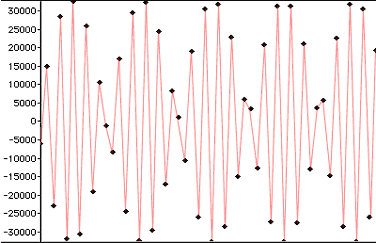
In practice, as the theoretical conditions cannot be perfectly respected, amplitude and frequency modulations are observed on the signal when its frequency approaches the Nyquist limit. The graph below shows the digital output of a 20 KHz signal on a CD-DA with the red approximation of the equivalent analog signal.
 |
| Digital output of a 20 KHz signal on a CD-DA. |
Measures
Drop-out
This measurement shows the behavior of a CD player during a drop-out (complete loss of the signal on the CD).
At first, interpolation allows to approximately recompose the original signal by keeping the right values instead of missing samples. Then the lack of correct points leads the player to freeze the signal on the last known sample.
CIRC Action
This case is particularly interesting because it shows precisely how the CIRC corrector behaves. We have seen that the frame recorded on the CD had the following shape: L1 L3 L5 R1 R3 R5 C2 C2 L2 L4 L6 R2 R4 R6 C1 C1.
But the samples are temporally mixed. If L1 belongs to the instant T, L3 belongs to the instant T + 8, L5 to T + 16, etc. The samples are temporally mixed. The sample R6 is thus the most delayed, so it is this one which will appear first in error.
We can therefore see on the image that the signal in error during a dropout appears first on the right channel (R), then in a second time on the left channel (L).
The correction system has replaced the missing samples by a null value (logical 0).
Buffer Action
This capture is even more exceptional, as it shows to the nearest byte how CIRC operates on a drop-out.
 |
| Buffer action on a CD-DA. |
The correction system used its buffer memory to connect the frames before and after the dropout. The samples assumed to be in error therefore take the value found in the connected frames (this explains the appearance of two out of phase sinusoids).
Each color band represents a frame of the right channel with its 6 samples R1 R2 R3 R4 R5 R6.
As we have already seen, the sample R6 is the first to be erroneous during the first 8 red frames.
Then it is the turn of sample R4 during the 8 yellow frames.
The next step, in green, shows the propagation of the error on sample R2. It lasts 16 frames since the next sample in error belongs to the left channel (L6).
Afterwards things speed up, since we should see the samples L4 L2 C2 before the appearance of R5.
But this is not the case and R5 appears in error at the same time as L4 (I don't have the explanation).
Parasites
These curves compare a noise on an analog disk (left curves) with a digital noise (right curves). The x-axis scale represents the number of samples on the CD.
 |
| Noise on an analog disk (left curves) with a digital noise (right curves). |
The analog noise is surrounded by damped oscillations and its total duration is about 8 ms. We had to amplify the signal strongly to make it clearly visible. Its real amplitude is therefore much lower. The spectral analysis shows an almost linear bandwidth from 20 Hz to 8 KHz. The spectral component above 8 KHz is practically non-existent. In spite of its low amplitude, this noise is very unpleasant because it creates a small slap characteristic of analog discs.
The digital noise is composed of a random series of binary values lasting 3 to 4 ms per channel (the amplitude has not been modified). As has already been observed, there is a shift between the right and left channels. The spectral analysis shows a linear bandwidth from 20 Hz to 20 KHz, so it can be assimilated to a perfect white noise. When listening, the digital noise seems more harmonious! However, it was necessary to draw a 3mm black line on the CD for it to appear.
Square signal
Apart from its correction capabilities, the CD has very impressive characteristics, as here in the reproduction of a square wave signal and a 400 Hz wave train. Perfect!
 |
| Square signal of a CD-DA. |
Wave train
An example of a wave train at 400 Hz shows that the signal is perfectly respected without visible distortion.


Comments
Post a Comment